
Control panel wiring diagrams are critical for understanding the electrical and control circuits within a control panel, used to manage and monitor various machine or system operations. These diagrams provide a clear visual representation of how components such as switches, relays, circuit breakers, and controllers are wired together to control machines or processes. In the UK, control panel wiring diagrams must adhere to national electrical standards to ensure safety, functionality, and compliance.
1. What Are Control Panel Wiring Diagrams?
Control panel wiring diagrams are detailed technical drawings that represent the electrical components and their connections within a control panel. These diagrams are used by electricians, engineers, and technicians to design, install, maintain, and troubleshoot control panels. In the UK, these diagrams must comply with standards such as BS 7671 (Wiring Regulations) and BS EN 60204-1 (Safety of Machinery – Electrical Equipment of Machines) to ensure safety and reliability.
2. Types of Control Panel Wiring Diagrams
Control panel wiring diagrams typically fall into a few key categories, depending on the complexity and functionality of the panel:
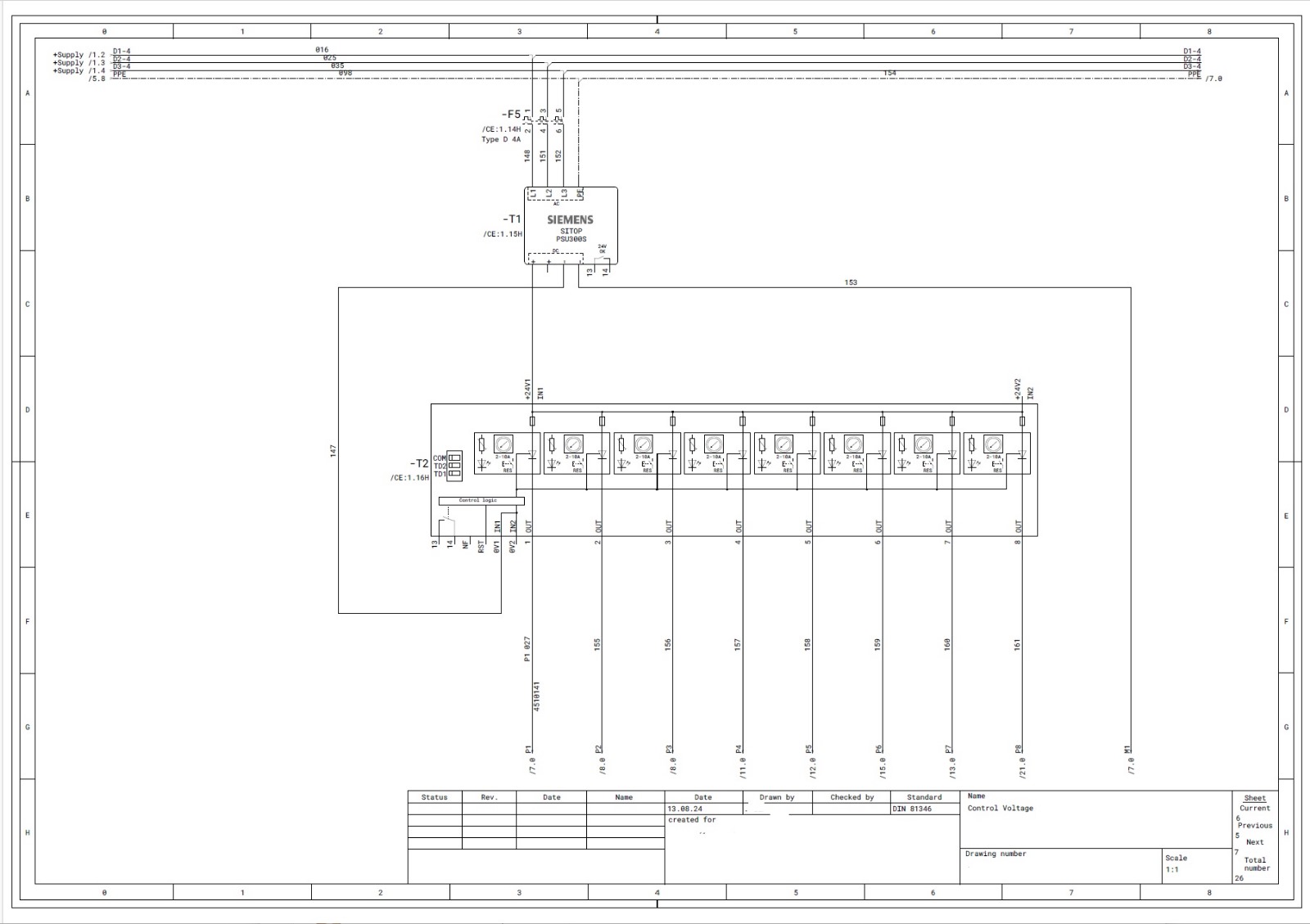
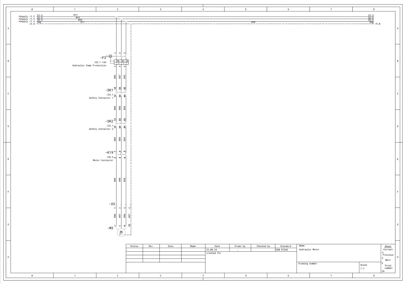
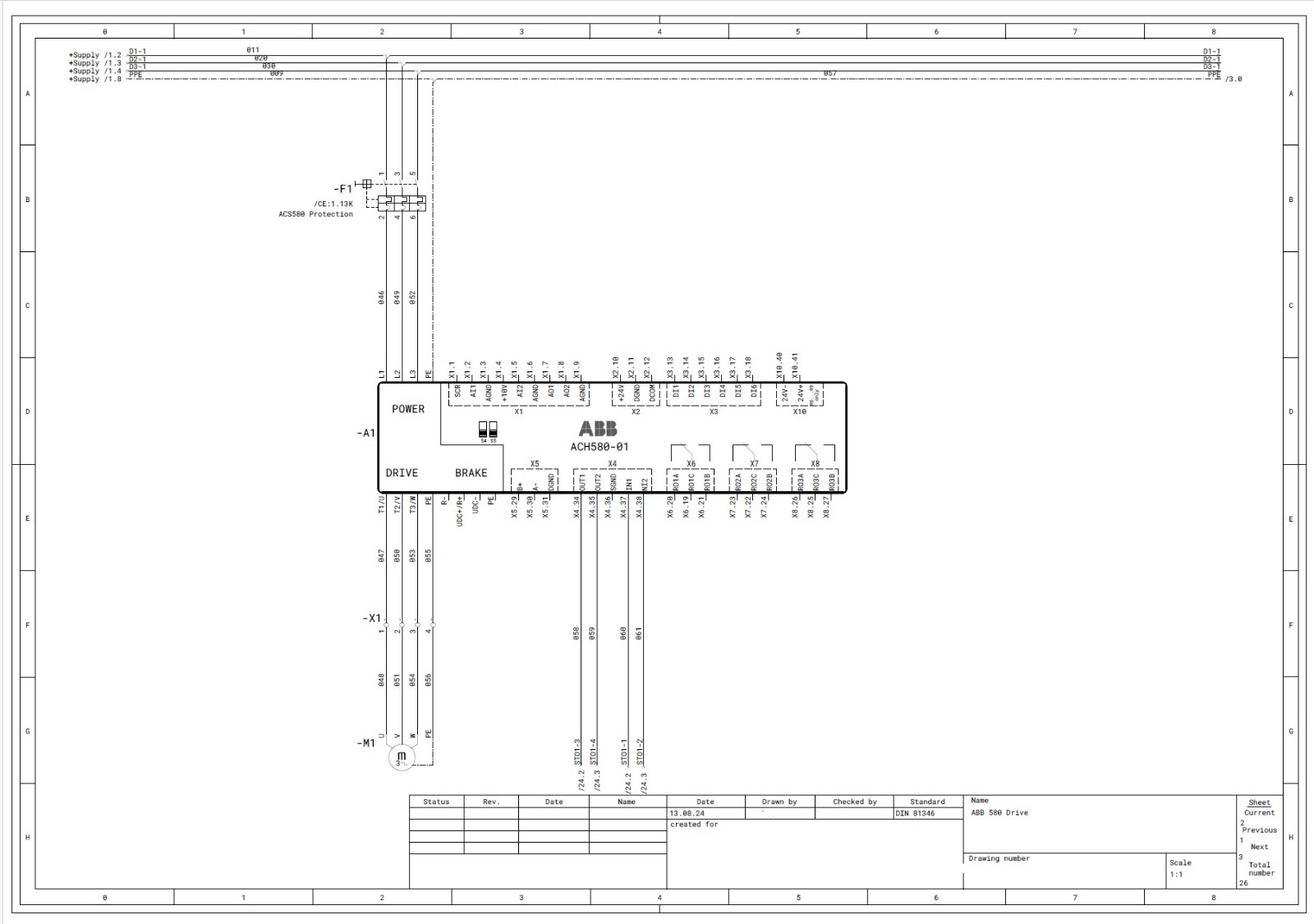
• Power Circuit Diagrams: These diagrams focus on the distribution of electrical power within the control panel, showing how power flows to key components like motors, transformers, and heating elements.
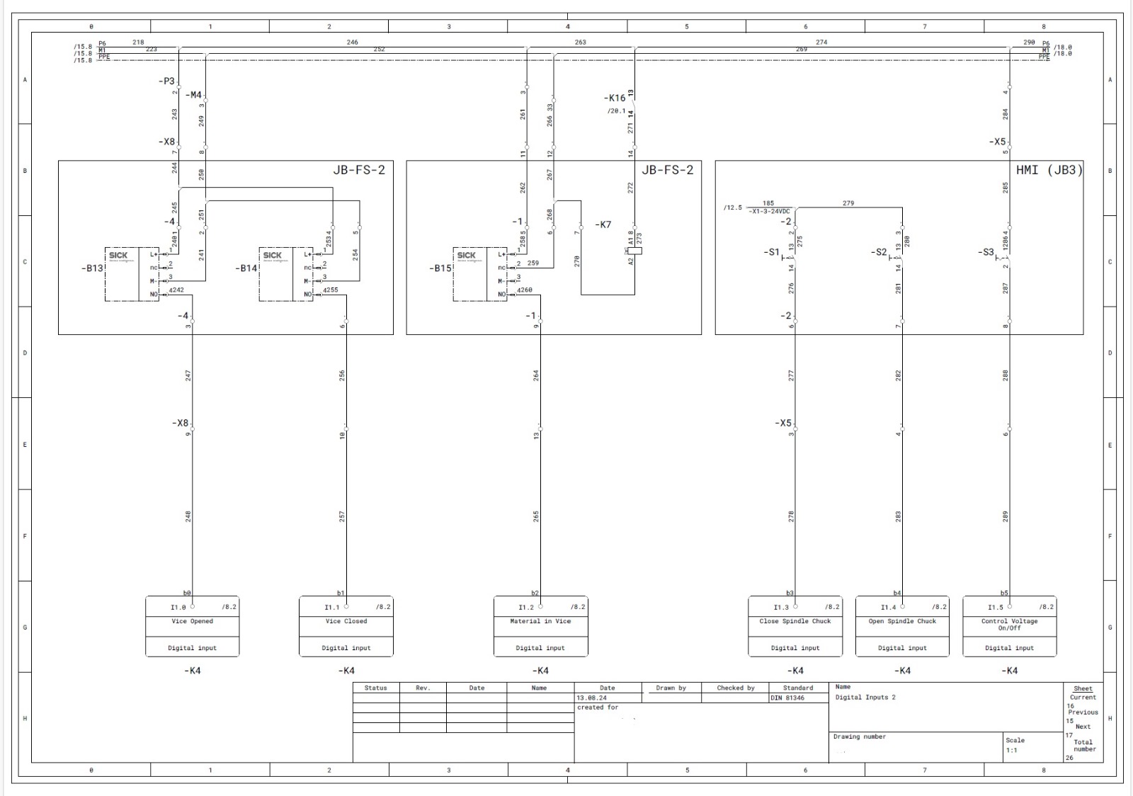
• Control Circuit Diagrams: These diagrams show the control circuits, including switches, relays, PLCs (programmable logic controllers), and other control devices. They detail how these components interact to control the operation of the system.
• Interlock and Safety Circuits: These circuits ensure safe operation by preventing unsafe conditions. Diagrams may include safety relays, emergency stop circuits, and other protective measures.
• Instrumentation and Monitoring Circuits: These circuits monitor various parameters such as temperature, pressure, or flow. The diagram will show sensors, transmitters, and other instrumentation integrated into the control panel.
3. Symbols and Notations (UK Standards)
Control panel wiring diagrams in the UK use standardized symbols to represent electrical components. These symbols are defined by BS 3939 and IEC standards and must be used consistently across control panel designs.
Some common symbols in UK control panel wiring diagrams include:
• Relays and Contactors: Represented by squares or rectangles with contact symbols, indicating the type of contact (normally open or normally closed).
• Push buttons: Shown as a circle with “PB” or “P” inside, with NO or NC contacts to indicate the button’s behaviour.
• Switches: Represented by a simple break in a line or a double line with a label such as “S” or a specific identifier.
• Fuses and Circuit Breakers: Fuses are represented by a square with a diagonal line through it, while circuit breakers are shown as rectangles.
• Motors and Actuators: Typically represented by the letter “M” inside a circle or a rectangle, with the motor type indicated (e.g., “M1” for motor 1).
• Indicators and Lights: Depicted by a circle with “L” or the symbol for a lightbulb to indicate an indicator light.
4. Reading the Wiring Layout
Control panel wiring diagrams in the UK are structured to show the logical connections between components and their relationships. Here’s how to approach reading these diagrams:
• Title Block: Located at the bottom or corner of the diagram, the title block includes important project details like the machine or panel name, drawing number, revision history, and date. It may also include the name of the designer or contractor.
• Power vs. Control Circuits: In control panels, power circuits (carrying current to motors, transformers, etc.) are typically shown with thicker lines, while control circuits (like relays, PLCs, or sensors) are represented with thinner lines.
• Component Locations: Components are often shown in a schematic layout to indicate their physical position in the control panel. This can be useful when wiring the panel or performing maintenance tasks.
• Wiring Paths: Lines represent conductors (wires) that connect components. The wiring should follow the logical sequence of operation within the control panel, and arrowheads may indicate the direction of current flow or the operation of components like relays.
5. Identifying Power and Control Components
In a control panel wiring diagram, components are divided into two main categories:
• Power Components: These components handle the electrical supply and distribution, including circuit breakers, fuses, motors, and transformers. Power components are usually connected with thick lines to indicate higher current-carrying capacity.
• Control Components: These components manage and regulate the operation of power components. They include switches, relays, sensors, push buttons, and PLCs. Control components are connected with thinner lines and are often used to automate machine processes or sequences.
6. Understanding Control Circuits
Control circuits are at the heart of most control panels, and understanding them is essential for reading the diagram:
• Start/Stop Circuits: Start/stop circuits use push buttons or switches to control the operation of motors or other equipment. Typically, a NO (normally open) start button closes the circuit to energize a relay or contactor, while an NC (normally closed) stop button opens the circuit to de-energize the device.
• Relays and Contactors: These components act as switches within the control circuit, opening and closing contacts to control the power circuit. In the UK, these components must meet BS EN 60947 (low-voltage switchgear and control gear standards).
• PLC Control Circuits: In automated systems, a Programmable Logic Controller (PLC) may be used to control the entire sequence of operations. The wiring diagram will show the PLC’s inputs (e.g., switches, sensors) and outputs (e.g., motors, actuators) along with the control logic for each operation.
• Overload Protection: Circuit breakers and overload relays are included in control panel wiring diagrams to protect the equipment from excess current, which could cause overheating or damage. The overload relay is typically wired to the motor circuit to break the connection if the current exceeds safe limits.
7. Wire Colours and Numbering (UK Standards)
The UK follows strict wiring colour codes to ensure consistency and safety in electrical systems. These colour codes are defined by BS 7671 and BS EN 60204-1 and are crucial for control panel wiring:
• Black: AC and DC Power Circuits
• Red: AC Live or Neutral via transformer
• Blue: DC+-
• Orange: Interlocks control circuits supplied from an external power source or remote panel
Wire numbering is also critical for ensuring proper identification of wires during installation and maintenance. Each wire will typically have a unique number or code, which corresponds to its role in the control circuit.
8. Safety and Compliance
Control panels in the UK must comply with BS 7671 (Wiring Regulations) and BS EN 60204-1 (Safety of Machinery – Electrical Equipment of Machines), which provide guidelines for safe electrical design. These regulations cover:
• Earth Fault Protection: The diagram must include provisions for grounding and earthing to prevent electric shock hazards.
• Emergency Stop Circuits: Emergency stop buttons must be clearly shown in the diagram, following specific regulations for safety.
• Overcurrent Protection: Circuit breakers or fuses should be specified to protect the control panel from overloads and short circuits.
9. Troubleshooting with Control Panel Wiring Diagrams
When troubleshooting a control panel, these wiring diagrams are invaluable tools:
• Identifying Faulty Components: Use the wiring diagram to pinpoint the location of malfunctioning components such as switches, relays, or fuses.
• Tracing Circuits: If a circuit isn’t working, follow the wiring diagram to identify any disconnections, faulty relays, or incorrect wiring.
• Verifying Connections: Ensure all components are correctly wired and that the connections match the diagram. Incorrect wiring can lead to equipment failure or electrical hazards.
10. Using the Legend and Key
Control panel wiring diagrams include a legend or key that explains the symbols, wire colours, and component labels used in the diagram. This is particularly useful for understanding the specific function of each component and ensuring proper identification during installation and maintenance.
Conclusion
Reading control panel wiring diagrams in the UK requires a good understanding of electrical symbols, circuit design, and compliance with BS 7671 and other relevant safety standards. These diagrams play a critical role in the installation, operation, and maintenance of control panels, ensuring machines and systems operate efficiently and safely. By mastering the skills to read these diagrams, you’ll be better equipped to design, troubleshoot, and maintain control panels in a wide range of industrial applications.


Recent Comments